
For my master’s thesis, I tackled a problem I find fascinating: making wireless charging smarter. This project is the summary of my work for the thesis titled, “Embedded Real-time Identification of Coupling Factor for Inductive Energy Transfer Systems.”
The idea is based on the fact that, Wireless Power Transfer (WPT) systems are incredibly sensitive to coil alignment. A small misalignment can drastically drop efficiency. I wanted to know: could I build a system using a low-cost microcontroller that could instantly measure this alignment in real-time?
This project was my answer.
It is a foundation upon which further research would be undertook, for use cases like valet parking and was done with the Institute for Electrical Energy Conversion (IEW).
Objective
The core problem was to design, build, and validate an embedded system capable of real-time parameter identification for a WPT system. Specifically, I focused on estimating the coupling factor (k), a key parameter that directly represents the physical alignment and magnetic coupling between the transmitter and receiver coils.
My goal was to implement this estimation could be done not just accurately (with < 5% error), but fast enough (in the millisecond range) to be used for live control, all while running on a resource-constrained STM32 microcontroller and identifying the effecting factors.

My Contribution
As this was my master’s thesis, I was responsible for the entire project lifecycle, from concept to final validation, along with supervision from the Institute. My work included:
- Algorithm Design: Developing the complete methodology, which uses an “impulse excitation” (a controlled 3-6µs pulse) on the WPT converter, to make the system “ring” like a bell. By analyzing the frequency of that ring, I could determine the coupling.
- System Simulation: Building high-fidelity simulation models of the WPT system (using both Series-Series and LCC-LCC compensation topologies) in MATLAB/Simulink and PLECS to prove the theory.
- Embedded Programming: Writing and optimizing all the C code for the STM32 microcontroller. This involved implementing the signal processing chain, configuring hardware peripherals, and integrating optimized math libraries.

- Validation & Testing: I followed a three-stage validation process:
- Simulation: Verified the physics in PLECS. This also helped me to prove theoretical possibilities.
- Processor-in-the-Loop (PIL): Fed “perfect” simulation data directly to my STM32 code to validate the algorithm’s correctness in isolation.
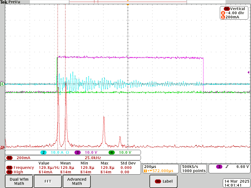
- Hardware Test Bench: Built a low-power (<1kW) WPT test bench with a Dual Active Bridge (DAB) inverter to prove the system worked in the real world, complete with noise and component imperfections.
Technical Details
- Hardware: STM32H7A3ZI-Q Development Board, Infineon Full-Bridge Inverters (DAB), Custom-Wound WPT Coils, Tektronix Oscilloscope & Current Probes, Silicon Labs Gate Drivers.
- Software/Libraries: C, MATLAB/Simulink, PLECS Blockset, ARM CMSIS-DSP Library.
- Key Concepts: Fast Fourier Transform (FFT), Digital Signal Processing (DSP), Impulse Response Analysis, Processor-in-the-Loop (PIL), Direct Memory Access (DMA), Dual Active Bridge (DAB), LCC-LCC & Series-Series (SS) Compensation.
Challenges & Learnings
This project was a fantastic lesson in bridging the gap between pure simulation and real-world hardware.
The eureka effect: Finding the Relationship
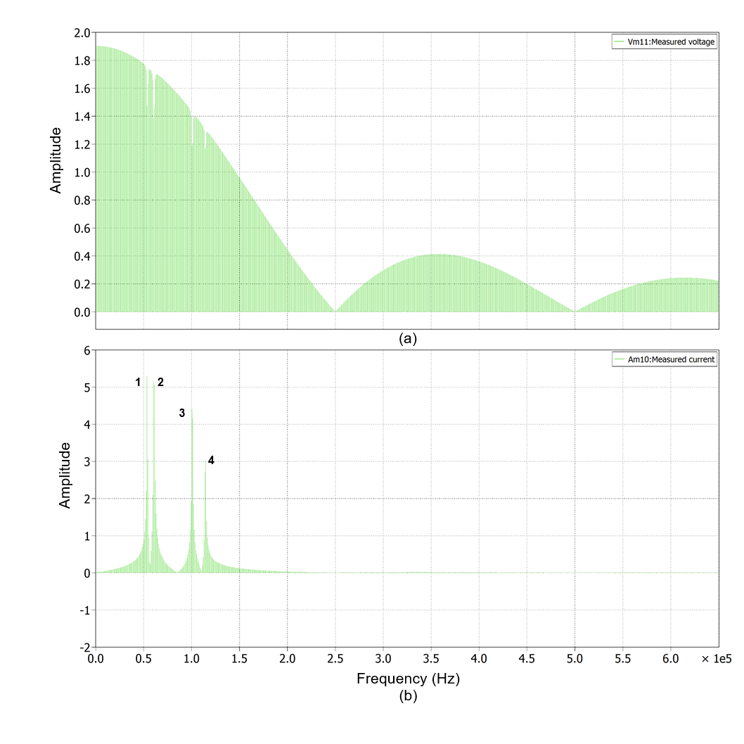
My first major finding was in simulation. By sending that impulse and analyzing the resulting current with a Fast Fourier Transform (FFT), a powerful math tool that breaks a signal into its component frequencies, I found a clear, predictable relationship. The frequency difference (Δf) between the resonant peaks in the signal’s spectrum had a stable cubic relationship to the coupling factor (k). This discovery was the key that made the entire estimation method possible.
It was observed that a SS compensation circuit gave 2 dominant peaks whereas a LCC-LCC compensated circuit gave 4 peaks.
Challenge: The Need for Speed
The biggest challenge was performance. An FFT is a computationally “heavy” algorithm. Running it in real-time on a microcontroller, which has limited processing power, is not trivial. A simple, non-optimized implementation would be far too slow.
Solution: Hardware Acceleration is needed
This forced me to dive deep into the STM32’s architecture. The solution was to stop the main processor from doing all the work:
- Direct Memory Access (DMA): I configured the DMA controller to autonomously capture the current sensor’s signal and place it into memory. The main CPU was completely free during this data acquisition.
- ARM CMSIS-DSP Library: I didn’t write my own FFT. Instead, I used the
arm_rfft_fast_f32function from the highly-optimized CMSIS-DSP library, which is tailored specifically for ARM Cortex-M cores and uses the chip’s Floating Point Unit (FPU).
The result was a success! My system could acquire the data and compute a 4096-point FFT in approximately 5 milliseconds, well within the real-time requirement.
My Key Takeaway: The Power of PIL Testing
When you’re debugging, it’s incredibly difficult to know if your code is wrong or your hardware is noisy. Processor-in-the-Loop (PIL) testing was the perfect solution. By feeding the “perfect” data from my PLECS simulation directly to my STM32 board, I could debug my embedded C code in a perfectly controlled environment. When it worked there, I knew my algorithm was solid, and any remaining issues were in the physical test bench setup.
More information about the project and documentations are available in my github.
This project proved that with smart algorithm design and by leveraging on-chip hardware accelerators, it’s entirely feasible for low-cost embedded systems to perform the complex, real-time analysis needed to make WPT systems more efficient and adaptive.